- Home
- Learn Linux
- Learn Electronics
- Raspberry Pi
- Programming
- Projects
- LPI certification
- News & Reviews

Google Ads
Resistors are normally labelled using 4 coloured bands across the body of the resistor. This consists three bands together indicating the resistance value of the resistor (ohms) and the forth, further away than the first three, is used to indicate the tolerance (accuracy) of the resistor. Some resistors have a 5th band which is used as a third significant figure.
The bands relate to the resistance as follows:
| 4-band resistor colour codes | |||
|---|---|---|---|
| Colour | Significant figures | Multiplier | Tolerance |
| Black | 0 | x100 | - |
| Brown | 1 | x101 | ±1% |
| Red | 2 | x102 | ±2% |
| Orange | 3 | x103 | - |
| Yellow | 4 | x104 | - |
| Green | 5 | x105 | ±0.5% |
| Blue | 6 | x106 | ±0.25% |
| Violet | 7 | x107 | ±0.1% |
| Grey | 8 | x108 | ±0.05% |
| White | 9 | x109 | - |
| Gold | - | x10-1 | ±5% |
| Silver | - | x10-2 | ±10% |
| None | - | - | ±20% |
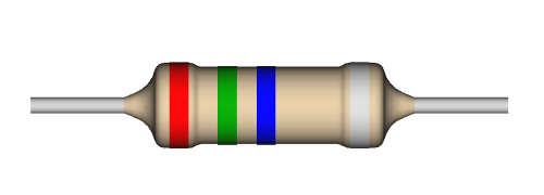
The example above has colours: Red, Green, Blue ... Silver.
This translates to 2 (red), 5 (green), x106 (blue), with a tolerence of 10%.
which is 25,000,000Ω or 25MΩ.
The tolerence is not normally a major consideration for most circuits, but if the exact value of the resistor is required then that band should be considered as well.
See the following video for an explanation about the resistor and color code.
For more details see guide to electronic components - resistors
Please view the copyright information regarding use of the circuits.

