- Home
- Learn Linux
- Learn Electronics
- Raspberry Pi
- Programming
- Projects
- LPI certification
- News & Reviews

Google Ads
This video explains about an electronics capacitor discharge unit, and how I designed my only variation for controlling model railway points.
In the UK we normally call them railway points, but a common term in the US is a railroad switch. They may also be known as a railway junction, or a railroad crossing.
In the model railway world then these are normally operated by solenoids. Some use servo motors, but this video is specifically for these solenoid point motors.
The video shows a 3D model of a solenoid model railway point motor in action, and explains about the advantages of a Capacitor Discharge Unit (CDU). This is part of a larger project which will involve use of a Raspberry Pi Pico to control point motors for a model railroad.
In the UK we normally call railway junctions as railway points, but a common term in the US is a railroad switch. They may also be known as a railway junction, or a railroad crossing.
For model railways, to avoid reaching across the layout it's advantageous to have some form of "remote" control. This could be purely mechanical with levers and wires, but is usually through some kind of electronic point motor. The most common of these are solenoid based, although it is possible to use servo motors or other forms of motors. This article is just about the solenoid types.
The image below shows a 3D model of a typical point motor. It has two coils on the underneath of a PCB. The two coils are coloured green and yellow on the model, although they are usually either black or the colour of the copper wiring in real life. The silver cylinder is known as an amature or plunger which moves from left to right towards whichever coil is energised. That is connected to the vertical pin which is what moves the level on the point.

When the coils are de-energized the pin will remain in it's new position helped by the point which is normally sprung. Latching solenoid point motors are also available, which are particularly useful for home-made points.

Point motors can be controlled by using a momentary toggle switch such as the one shown here. This is Single-Pole-Double-Throw (SPDT) switch with centre off. Which can also be described as (on)-off-(on). When in the centre then it is off, but when moved to either side it will connect between the common terminal and the pin associated with that direction. When released the switch will return to the centre off position.
This can be used with the following circuit to move the point the appropriate direction.

There are a few disadvantages for this circuit, the main things are that if you hold the switch closed for too long then it can result in burning out the coil and that there could be a large in-rush current when the solenoid is first energized meaning that you need to have a overspecified power supply. The in-rush can also result in large spikes which can have a negative effect other electronic circuits.
The capacitor discharge unit overcomes this by first storing a charge into a capacitor and then using that to switch the solenoid. It also improves the switching due to the amount of energy that can be provided for the short period of time needed to switch the points.
The aim of the capacitor discharge unit is to reduce the spike from the mains power supply and also to provide a high initial current which makes a reliable switch action. To do this you need some way of charging the capacitor, but then preventing excess current from flowing from the supply when the solenoid switches on. The traditional circuit uses a bipolar transistor, but I decided to create my own variant based around an N-Channel enhancement type MOSFET.
Below is the circuit diagram for my MOSFET based capacitor discharge unit (click the image for a larger version).
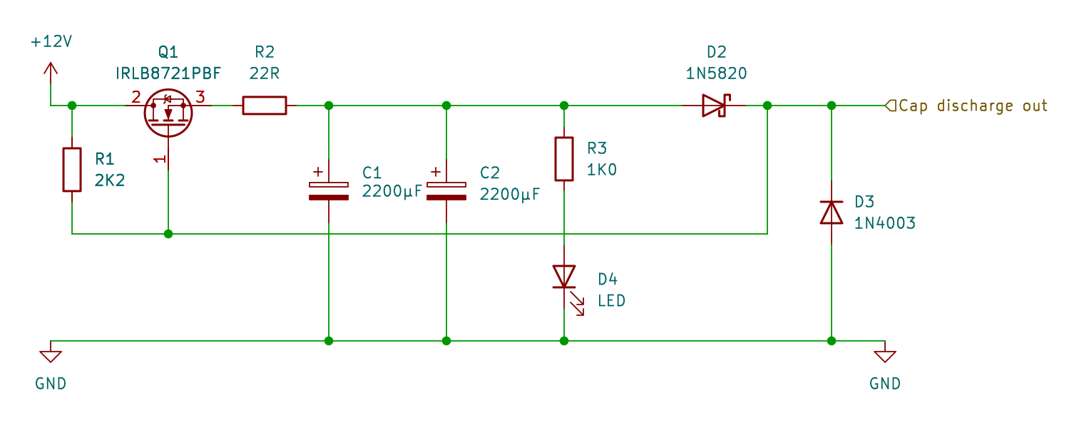
A full explanation is provided in the video above, but here is a quick summary.
I went through various iterations of design to come up with the final design.

These are some of the components I chose.
The diagram says 12V indicating a 12V power supply, but it can be up to 20V. Different solenoids need different voltages and I found the 12V would not be sufficient for some of my solenoids, so instead I used a 19V power supply
The two capacitors C1 and C2 are connected in parallel providing the sum of their capacity. I initially tried with 2 x 1000μF capacitors. I found that 2 x 2200 μF capacitors worked better, alternatively a single 4700μF capacitor could be used, or for a more powerful "kick" then 2 x 4700μF capacitors could be used.
A 1N5820 was used to allow the high current from the initial surge. This is also a schottky diode having a low voltage drop. The leads for the diode were too large for the breadboard that I used to prototype the circuit so I soldered a short length of solid core wire to the legs.
A similar diode was used for D1 (not shown) which is used between the power supply and the capacitor discharge unit. This diode could be used to allow this to be used with an AC supply or to protect against reverse voltage.
A 1N4003 diode was chosen as a flyback diode due to it's good tolerance against voltage spikes.
Although initially created and tested as a standalone project this will be used in creating a electronic switch control system, which will most likely be controlled using a Raspberry Pi Pico W.
More details coming soon, including integration into computer control system. Please follow my YouTube channel - penguintutor for future updates.
For more information see my Model Railway projects using Raspberry Pi, PicoW and alternative microcontrollers.
Please view the copyright information regarding use of the circuits.

