- Home
- Learn Linux
- Learn Electronics
- Raspberry Pi
- Programming
- Projects
- LPI certification
- News & Reviews

Google Ads
A voltage divider (also known as a potential divider) is a way of sharing a voltage. Typically two or more resistors are used. It is useful in many electronic circuits.
You may also see capacitors or inductors instead of resistors, particularly for AC inputs or fluctuating signals. For this video is just going to cover DC circuits with basic resistor voltage dividers.
Details are explained in the following video.
The basics of the circuit are shown in the diagram below. In this case this is acrosss a 5V power supply, although this could also be used across a different signal. There are two resistors of equal value and the voltage between those resistors is half of the supply voltage, 2.5V.
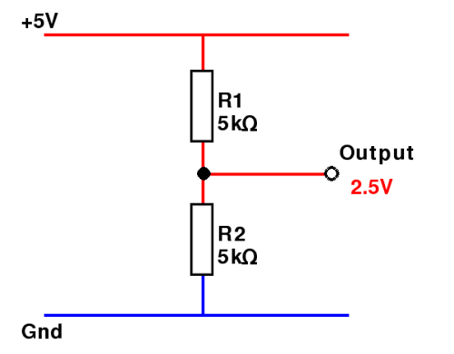
The formula showing the relationship between the resistors and the output voltage is shown here:

If you determine one resistor then you can calculate the second resistor using the following forumula:

A simpler way to calculate resistor values is to consider them as a ratio. If R2 is twice as big as R1 then the output will be 2/3 of the input voltage.
A potentiomter can be used as a voltage divider by connecting it across the power supply and taken the analog output from the centre pin. This is useful for a volume control, or to determine the speed of a DC motor etc. A useful value is a 10kΩ linear potentiometer.
An example circuit has been created which uses a potentiometer as a voltage divider to create an analogue voltage. This can be passed into the analog input of an Arduino (Arduino UNO in this case).
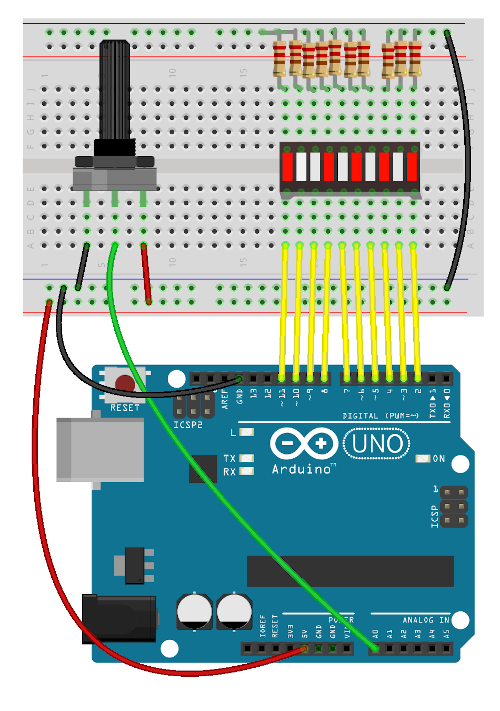
The arduino reads in the value which will be a value between 0 and 1023. If you wanted to know the voltage then divide the voltage by 1023 and then multiply it by the voltage.
In the Arduino sketch the input is divided by 1013 (less than the 1023 so that the top bar graph element lights up before the very end of the scale) and multiplied by 10 for the 10 elements of the bar graph display. This is shown in the code for the sketch below:
int pin_start = 2;

int analog_input = 0;

int bar_value = 0;


void setup() {

  // put your setup code here, to run once:

  Serial.begin(9600);

  for (int i=0; i < 10; i++) {

    pinMode(pin_start+i, OUTPUT);

  }


}


void loop() {

  // put your main code here, to run repeatedly:

  analog_input = analogRead(A0);

  Serial.println(analog_input);

  bar_value = (analog_input * 10 / 1013);

  Serial.println(bar_value);


  for (int i=0; i < 10; i++) {

    if (bar_value > 9-i) {

      digitalWrite(pin_start + i, HIGH);

    }

    else {

      digitalWrite(pin_start + i, LOW);

    }

  }


  delay(500);

}
For more details about the Arduino see Arduino getting started guide
Please view the copyright information regarding use of the circuits.

