- Home
- Learn Linux
- Learn Electronics
- Raspberry Pi
- Programming
- Projects
- LPI certification
- News & Reviews

Google Ads
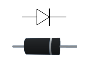
Now we get to look at our first semiconductor, which is a device that behaves differently depending upon certain conditions. In this case we are going to look at the most basic semiconductor device called a diode, and specifically a rectifier diode.
One of the most fundamental components in any electronic circuit is the diode. In the video above , we explore exactly how diodes work, the physics behind the P-N junction, and the different types of diodes you will encounter in your projects.
At its simplest, a diode acts as a "one-way valve" for electricity. It allows current to flow easily in one direction while blocking it in the other. This direction is determined by the component's polarity: current flows from the Anode (+) to the Cathode (-).
To understand why a diode behaves this way, we look inside the semiconductor material. A diode is created by joining a P-type region (positive holes) and an N-type region (negative electrons).
Depletion Region: Where these two materials meet, a "depletion region" forms, creating a built-in potential barrier that stops current from flowing freely.
Forward Bias: When we apply enough voltage to overcome this barrier (typically 0.6V–1.0V for silicon diodes), the "valve" opens, and current flows.
Different applications require different diodes. In the video, we compare several common types:
The video concludes with a demonstration of a Half-Wave Rectifier. By placing a diode in series with an AC signal, we block the negative half of the waveform, effectively converting alternating current (AC) into pulsating direct current (DC).
For an improved circuit see the follow-up Full-wave bridge rectifier tutorial.
Usually the current is completely blocked in the reverse direction and we need to keep the reverse voltage below the breakdown voltage. However the zener diode is a specialised diode designed to allow current to flow not only in the standard forward direction but also in reverse when a specific voltage threshold, known as the Zener voltage, is reached. Unlike a standard diode, which blocks reverse current and can be destroyed if forced to conduct, a Zener diode is engineered to safely operate in this "breakdown" region. When the voltage across it exceeds its rated zener voltage, it acts like a pressure relief valve, conducting current to maintain that steady voltage level across its terminals. This unique property makes it a useful component for voltage regulation, where it is used to stabilize power supplies and protect sensitive circuits from voltage surges.
Please view the copyright information regarding use of the circuits.

