- Home
- Learn Linux
- Learn Electronics
- Raspberry Pi
- Programming
- Projects
- LPI certification
- News & Reviews

Google Ads
In this tutorial, we transition from the basic single-diode half-wave rectifier to the industry-standard full wave bridge rectifier. While a half-wave rectifier is inefficient because it "throws away" the negative half of the AC cycle , a bridge rectifier is designed to harvest every bit of energy by "flipping" the negative cycle into a positive one.
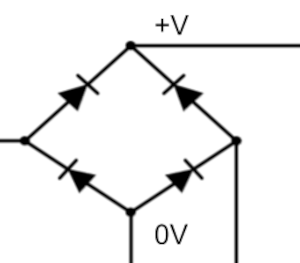
The circuit consists of four diodes arranged in a specific diamond pattern.
The Input: Incoming AC power is connected to the left and right nodes of the diamond.
The Output: Positive DC voltage is pulled from the top node, while the common ground is at the bottom.
The Path: During each half of the AC cycle, current is forced through a specific pair of diagonally opposite diodes. This ensures that even when the AC input reverses direction, the current through the load stays exactly the same.
Even though a bridge rectifier captures both halves of the wave, the resulting power is still pulsing DC. On an oscilloscope, you will see the frequency of these pulses double (e.g., from 50Hz to 100Hz).
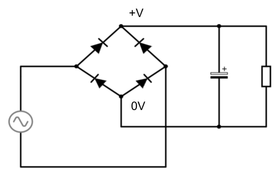
To make this power suitable for sensitive electronics, we use a smoothing capacitor. The size of the capacitor depends upon the frequency current and amount of ripple that is acceptable. Typically a capacitor of 1000μF or more is used.
There is a simple formula which can be used to calculate the actual size of the capacitor required.
C = Capacitance (Farads)
I = Load Current (Amps)
f = AC Input Frequency (Hz)
Vpp = Desired Peak-to-Peak Ripple (Volts)
Note: The value of 2 in this formula takes into consideration that the output to the bridge-rectifier is twice the frequency as the input. Just use the frequency of the input (eg. 50Hz for the UK electricity supply.
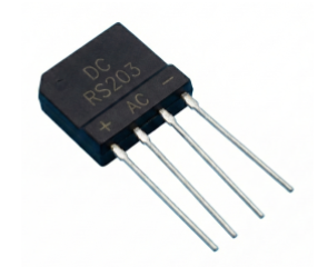
While you can build this circuit using four discrete diodes, it is most common to use a pre-made bridge rectifier unit. These components typically feature four pins clearly marked for AC input and DC output. In our demonstration, we used the RS203, which is rated for up to 200 volts and 2 amps. Note that there is a small "tax" for this process: a voltage drop (typically around 1.1 volts) because the current must always pass through a pair of diodes.
Please view the copyright information regarding use of the circuits.

