- Home
- Learn Linux
- Learn Electronics
- Raspberry Pi
- Programming
- Projects
- LPI certification
- News & Reviews

Google Ads
Be sure to check out the accompanying video above to see these circuits built on a breadboard and tested live on an oscilloscope!
In our previous project, we explored how to convert an AC power supply into DC using a full-wave bridge rectifier, smoothing out the voltage peaks and troughs with a 1000µF capacitor. While this provided a fairly stable 19V output, it left us with an unregulated power supply.
Unregulated supplies suffer from two main issues: residual voltage ripple and voltage droop under load. In this guide, we will look at how to solve these problems using a linear voltage regulator—specifically, the LM7812—to create a stable, clean power source safe for your electronic projects.
Before fixing the problem, it is helpful to visualise it. When viewing the smoothed output of our bridge rectifier on an oscilloscope, it initially appears as a flat, steady line. However, a closer look reveals imperfections.
By switching the oscilloscope to AC coupling, we remove the underlying DC component and isolate the voltage fluctuations. This reveals a ripple of just under 200mV.
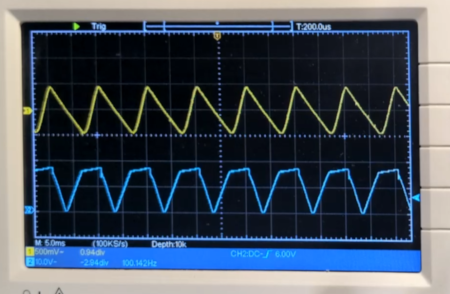
Furthermore, unregulated supplies are highly sensitive to load changes. In our initial tests with a high-value resistor (simulating a low load), the voltage sat at 19V. When a heavier load is applied, the voltage drops considerably—down to 17V in our test case—and the ripple increases. While increasing the smoothing capacitor's value can marginally reduce ripple, it does not fix the underlying voltage instability.
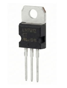
To achieve a rock-solid output, we can add a linear voltage regulator to the circuit. The LM78xx series is a very common family of linear voltage regulators. The naming convention is straightforward: the "78" denotes a positive regulator, and the final two digits indicate the output voltage.
Below is the schematic diagram for our regulated power supply, created in KiCAD.
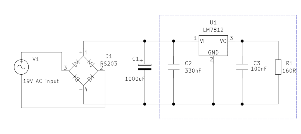
The section outlined by the blue dashed line highlights the new regulatory components. Alongside the LM7812 itself, you will notice two additional decoupling capacitors: a 330nF capacitor on the input and a 100nF capacitor on the output. These specific values are recommended by the manufacturer in the component's datasheet to stabilise the output and prevent high-frequency oscillations.
When this circuit is tested on the oscilloscope, the results are immediate. The output remains locked at a constant 12V regardless of whether a load is applied, and the 200mV ripple is entirely eliminated.
When working with components like the LM7812, consulting the manufacturer's datasheet is essential. One of the most critical specifications to understand for a linear regulator is the Dropout Voltage.
The dropout voltage is the minimum voltage difference required between the input and the output for the regulator to function correctly. For the LM7812, the dropout voltage is typically around 2V. This means the input voltage must be at least 2V higher than the target output. To get a stable 12V out, you must feed the regulator at least 14.5V to 15V. Because our unregulated supply only dropped to 17V under heavy load, it remains comfortably above this threshold.
Linear regulators maintain a stable output by burning off excess voltage as heat. This is their primary disadvantage. If you are dropping 19V down to 12V, the regulator must dissipate the 7V difference. Under high current loads, these components can become exceptionally hot and require external heatsinks.
For higher power applications, switching regulators (like buck or boost converters) are far more efficient, though they are more complex to design.
While the LM7812 looks like a simple three-pin black box, it is based on fundamental electronic principles. A basic linear regulator requires two things: a reference voltage and a pass transistor.
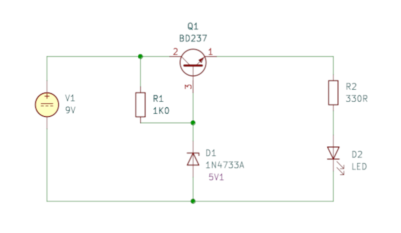
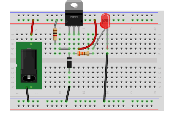
If you build this discrete circuit, the final output voltage is determined by the Zener diode minus the inherent voltage drop of the transistor's base-emitter junction (typically about 0.7V for silicon transistors). The relationship is expressed as:
Vout = VZ - VBE
For example, if you use a 5.1V Zener diode as your reference, the output voltage would not be exactly 5.1V. Subtracting the 0.7V transistor drop leaves you with a regulated output of approximately 4.4V.
While building a discrete regulator is a great educational exercise, we almost always use dedicated integrated circuits like the LM7812 in practical applications.
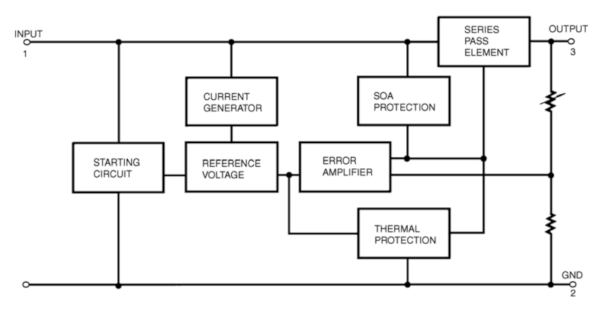
As shown in the internal block diagram, the LM78xx series packs dozens of miniaturised components into a single package. It builds upon the basic Zener and transistor concept but adds highly accurate voltage references, built-in short-circuit protection, and thermal shutdown mechanisms to prevent catastrophic failure. It does all the hard work for us in one tiny, reliable package.
For an example of a voltage regulator in use see my Model Railway Point Controller project. That example uses an LM7805 to drop a 12V input supply to 5V for use powering a Raspberry Pi Pico.
Also see my electronics guide on Powering the Raspberry Pi Pico.
Please view the copyright information regarding use of the circuits.

