- Home
- Learn Linux
- Learn Electronics
- Raspberry Pi
- Programming
- Projects
- LPI certification
- News & Reviews

Google Ads
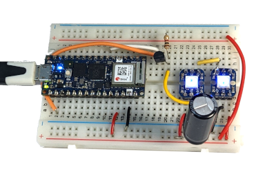
This project creates a wireless Internet controlled NeoPixels / PixelStrips using an Arduino Nano RP2040 Connect Microcontroller.
This is an alternative to my Raspberry Pi PixelStrip / NeoPixel project. This is designed around the Arduino Nano RP2040 Connect Microcontroller, which is Arduino's alternative to the Raspberry Pi Pico.
The Arduino Nano RP2040 Connect is a microcontroller based around the Raspberry Pi RP2040 (as used in the Raspberry Pi Pico). Unlike the Pico which is a low cost basic board, Arduino has packed in lots of additional features. This includes more flash RAM but more significantly for this project a built in ESP32 wireless controller.
I've already explained this in more details at Getting Started with the Arduino Nano RP2040 Connect and more about the ESP32 at Getting started with the ESP32 with Wi-Fi and Bluetooth.
When I refer to NeoPixels or PixelStrips then these are effectively RGB LEDs with a built-in WS2811 or WS2812B controller. These LEDs can be chained together with the output of the first LED going to the input of the next LED. These are often combined into strips, squares or other shapes. The controllers for the LEDs pass data through to subsequent LEDs making each LED individually addressable based on their position in the chain.
The Arduino Nano RP2040 uses 3.3V on the GPIO pins, unlike the original Arduino models which used 5V. This means that the output of the Arduino needs to be increased from 3.3V to 5V. You could skip this, but that may not always work as I have experienced previously with the Raspberry Pi. I therefore recommend using a voltage level-shift or a voltage buffer.
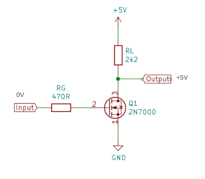
My first attempt was using a MOSFET inverting buffer which is what I normally use with the Raspberry Pi. This relies on the code inverting the signal before it is sent to the GPIO port. Unfortunately whilst this is an option for the Raspberry Pi libraries, it is not included in the NeoPixel libraries available through the Arduino library manager. The diagrams below show an inverting MOSFET buffer and the oscilloscope waveform.
I also tried a series MOSFET non-inverting level shifter. This worked well initially, but offered no protection to the Arduino in the event of a short circuit. As a result of a faulty LED it damaged a GPIO port on the Arduino RP2040. As a result I decided against this (see the video below for more details).
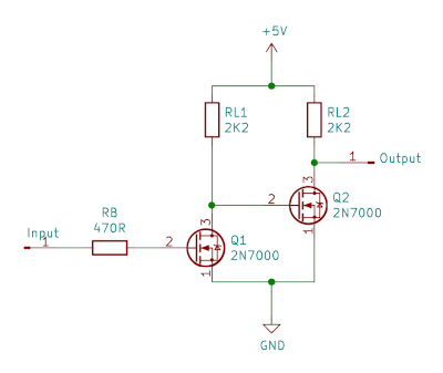
An alternative is to send the output of the MOSFET inverting buffer through another inverting buffer. This inverts the inverted signal resulting in a non-inverting buffer. The diagrams below shows the two-stage MOSFET buffer and the waveform captured on a logic analyser.
I originally connected to pin D2 (GPIO 25), but found that to conflict with the Wireless signal through the ESP32. I therefore moved the connection to pin D3 (GPIO 15) which cleared the problem. For the PCB I am using pin D5 (GPIO 17), this is due to the damage to pin D3 (as mentioned in the video below), but also allows more compatibility between different Arduino models.
The first version of the code was created to just change the colour of all the pixels to a single colour. This basic code is based on the Arduino WiFi LED code and the AdaFruit NeoPixel Arduino library. It is a simple example which turns all the LEDs a single colour based on 3 on and 3 off buttons. This gives a total of 8 different colour combinations.
![]()
The code is left here as a demonstration of the basic operation of the code, but I recommend you use the newer version of the code listed later in this page.
This code is available to download below.
The code above is just a demonstration of how to get started. In future I'll be creating a version with lots of different sequences that can be used. To find out more as the project progresses please subscribe to my YouTube channel (PenguinTutor) and click the notification bell to get notified. Alternatively you can follow PenguinTutor on social media using the links below.
Before I decided on the two-stage non-inverting MOSFET buffer I had tried using a series connected MOSFET non-inverting buffer. Whilst this worked I now feel that the two-stage buffer offers better protection against a faulty LED.
This is explained in the following video, where I also confess about the false bug report that I submitted (which was in good faith before I realised I had a faulty pixelstrip).
This video goes through the improved software code which is able to provide different colour sequences. This is a long video explaining about different aspects of how this works but it is split into chapters so you can jump to the relevant section.
I was originally planning to create the code in MicroPython, however at the time I created the code that was not available for the Arduino Nano RP2040. I therefore wrote the code in the Arduino's native C++ instead. This is more complicated to follow than if it was MicroPython, but does have the advantage of supporting different devices including: Arduino UNO WiFi, the Arduino Nano 33 IoT, and the Arduino MKR series boards that have WiFi.
![]()
The way that the code is implemented allows you to use this is home automation. The video shows how you can get the URL for the selection using the Arduino serial console monitor and then control the lights using wget. This can then be included in crontab for simple automation tasks.
Visit the GitHub Arduino Pixels page for the lastest version of the source code.
For more details about the automation see my guide to scheduling jobs in crontab.
The next stage was to create a custom PCB in KiCAD.
This part of the project was sponsored by JLCPCB who manufactured the PCBs for this project. See the JLCPCB guide for exporting from KiCAD.
Sign up on the above link for a $30 in coupons towards your future PCB requirements.
This video shows the design process in creating the PCB. It explains about some of the design decisions, shows how to create the PCB using KiCAD and then shows how the components were soldered to the PCB. This explains about some of the problems I experienced and includes suggestions for future improvements, including an updated footprint to make soldering the MOSFETS easier.
The version available for download is the lastest version including updates to the footprints for the MOSFETS.
The original design was based around using the Arduino connected to an existing wireless network. This was OK when used at home, but meant that it was not possible to use the WiFi RGB LED server away from home. Whilst it was easy enough to configure the ESP32 (using WiFiNINA) as an access point I needed a way to store the Jquery and JqueryUI files on the flash storage and serve them up to the web clients. I eventually implemented this by embedding the jquery file into a C++ header (.h) file and copying that into the RP2040 RAM before sending it to the web client.
My first attempt at that resulted in significant performance issues, which I identified as being due to the web server sending only 1 byte at a time to the client. By buffering the information 1000 bytes at a time I found I was able to improve performance by over 100 times. This is explained in the video below.
This is also explained in further details at guide to programming using the flash memory of the Ardiuno RP2040 in C++.
The final step is to create an enclosure to mount the PCB and circuit inside. I've designed the enclosure in FreeCAD and 3D printed it. I used standard PLA for the enclosure, but included a gasket which I 3D printed out of TPU to provide additional waterproofing.
For more information see my post on the enclosure at: Designing an Outdoor Enclosure for an Arduino RP2040.
If you would rather use a Raspberry Pi you can see my related project on Raspberry Pi Pixel Server.
See my Maker projects, including Raspberry Pi and Arduino projects.
To find out about the updates please:
Subscribe to the PenguinTutor YouTube Channel
and
Follow @penguintutor on Twitter
Please view the copyright information regarding use of the circuits.


