- Home
- Learn Linux
- Learn Electronics
- Raspberry Pi
- Programming
- Projects
- LPI certification
- News & Reviews

Google Ads
In the previous pages I have explained how you can use an off-the-shelf pre-built Arduino or compatible board. In this I'm going to go further to explain more about the circuit that is used on the Arduino and how you can create your own custom circuits which are also based around the ATMega ATMEL microcontrollers.
The circuit is actually very simple. As long as you buy a ATMega microprocessor with the bootloader pre-installed then you only need a few components to create the basic circuit which you can then connect up to external devices.
The projects used in these videos are based on the Shrimping Kits which used to provide kits for creating your own circuits. These are no longer available, but you can buy the components individually from other suppliers and still follow the projects. Do NOT attempt to buy these kits from the Shrimping website as they no longer stock the kits. Instead see the following details of how to buy ATMEGA328P with bootloader and other components.
In the video I go through the process of creating the first kit, known as Blink. This creates a barebones circuit which allows you to program the ATMega and to get your first programming running.
This goes through the steps in creating a clone of an Arduino UNO / Arduino Duemilanove. This covers the main parts of an Arduino circuit, excluding the UART used for the USB / serial interface and a stable power supply circuit. The UART is still required, but is connected externally instead using a pre-built UART, and the power supply is taken from the Raspberry Pi USB port or can be connected to an external power supply.
The circuit diagram is shown below. This is the basic schematic of some of the components that are used in the Arduino boards such as the Arduino UNO. Those boards do have additional components including the UART and power supply which are not included in this image.

This project shows the alarm clock project which builds on the basic Arduino circuit. It then adds a custom output display based around 24 LEDs. 12 LEDs for the hours and 12 for the minutes. In the circuit these are all built on a breadboard so they are in two rows, but could instead be placed into a circle to look more like a traditional clock, or could be used to light up words for a word clock.
If you follow this project you will learn how an Arduino works, how to add a real-time clock and a buzzer and then a shift-register and constant current LED driver. You will also see how to program these using the Arduino IDE. Through this you will also learn about prototyping a circuit using a breadboard.
The real-time clock is provided using a DS1307 IC with CR2032 button cell battery backup and 32.768kHz crystal.
Sounds are created using a Piezo buzzer.
The shift register and constant LED driver is provided by a pair of a DM134 ICs.
The schematic circuit diagram is shown below.

For more details about how the Shift-Registers work (although using different ICs) see introduction to digital electronics or my Digital electronics Shift-register video
This is the final circuit of the kits that I've created as in future I plan to create my own circuits instead. In this I used it to demonstrate the use of a strip board / perma prototyping board used to solder a permanent circuit.
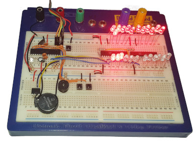
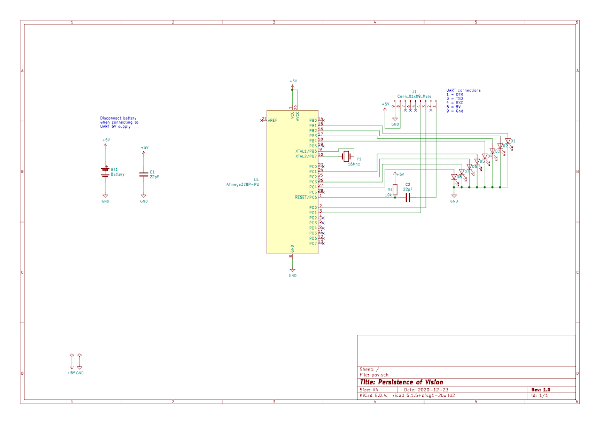
This project uses light painting using just 8 LEDs and a camera with a slow shutter speed to create images and writing. This is made using a ATMega328p which is soldered onto a stripboard circuit.
This is based around a breadboard design I've soldered onto a perma-prototyping board. The board is a type of copper stripboard which is arranged similar to a breadboard layout making it super easy to transfer a design from a breadboard to a permanent soldered solution.
Components required
The circuit diagram is included below.
I'll be adding new projects based around my own custom circuits in future.
I also plan to design my own custom circuit based around the ATMel ATMega328P which I'll be creating on a custom designed printed circuit board (PCB)
.To be notified about future videos
Subscribe to the PenguinTutor YouTube Channel
Please view the copyright information regarding use of the circuits.

