- Home
- Learn Linux
- Learn Electronics
- Raspberry Pi
- Programming
- Projects
- LPI certification
- News & Reviews

Google Ads
Digital electronics is the basis of how computers and microprocessors work. This video series explains some of the basic principles of digital electronics.
This video explains about logic gates which are the basic building block of digital circuits.
This video explains about combinational logic circuits where multiple logic gates are connected together to make a useful circuit. The specific example used is the adder, it shows first how a half-adder works, then expands this to a full-adder. Finally multiple full-adder circuits are connected to create an 8-bit adder. The video shows the different logic values as they propogate through. It also explains why the ripple adder is slow and about fast adders.
The previous video covered combinational logic where different logic gates can be combined to create another circuit. In that case you could know the output of the circuit by looking at the state of the inputs. Sequential logic follows a similar concept of joining together multiple logic gates, but now introduces a state. It uses a feedback loop which can remember the current state of the circuit. This provides a form of memory where the circuit remembers the state.
The basic circuit component of sequential logic circuits is the flip-flop. This covers a simple flip-flop and then the SR / RS flip-flop and the D flip-flop. These flip-flops can then be combined to create a register, similar to how registers in a computer are used to hold informaiton withing the processor for use in calculations or to track the program flow, such as the program counter.
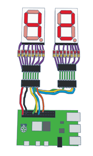
In the video on Shift Registers I have shown a LED 7-Segment counter. Unlike the other videos in this series this one actual shows a working digital circuit creating a numeric display which can connect to the Raspberry Pi and the Arduino. This project is complete with circuit diagrams for the Raspberry Pi and Arduino along with the source code.
The circuit diagram is included below. This is designed so that it can be constructed on a breadboard and so uses the SN74HC595 IC. This particular variant of the shift register is available as dual in-line package (DIP) suitable for use on a breadboard, but is designed for only driving 6mA loads on each of the outputs which is insufficient for the 7-segment display used. There are versions of the 74HC595 which can drive the LED without the ULN2803A Darlington transistor array, but they are typically available as surface mount components or mounted onto boards that are not suitable for connecting to a breadboard. You can see the technical information regarding the breadboard friendly version on the Texas Instruments SN74HC595 technical information.
The 2nd power supply, VCC2, is shown on the diagram as a separate power supply. If just driving the two 7-segment displays then that could be connected to the Raspberry Pi 5V pin (physical pin 2 or 4) or the 5V supply on the Arduino. If you extend the circuit using more shift registers, or would like to use this circuit for driving larger loads then it should be connected to an alternative 5V power supply.
The second edition of my book "Learn Electronics with Raspberry Pi" now adds a section on Digital Electronics which compliments this page this with more details about driving digital electronic circuits using a Raspberry Pi.
To be notified about future videos
Subscribe to the PenguinTutor YouTube Channel
Please view the copyright information regarding use of the circuits.

