- Home
- Learn Linux
- Learn Electronics
- Raspberry Pi
- Programming
- Projects
- LPI certification
- News & Reviews

Google Ads
The transistor is an amplifier, which can increase the amount of current flowing through a circuit. It can be used as a switch by only using the transistor in an off state or an on state using the transistor's saturated region. As a switch the transistor is often used to take a signal from a digital circuit and use it to switch larger loads than the integrated circuit (IC) can provide.
The circuit below shows a common simple configuration for a transistor switch circuit. It comprises of one NPN transistor, and depicts two resistors. The resistor RL is not necessarily a resistor, but represents the resistive value of a device that is being switched. This could be a lamp or relay or some other device that needs a larger current than the input is able to drive directly. A resistor may be needed if the device being switched does not have sufficient resistance of it's own (eg. LEDs). The resistor at the base Rb is a resistor used to prevent damage at the base of the transistor. This needs to be large enough to prevent damage to the transistor, but should still allow sufficient current to ensure the transistor switches on. Details of how to determine the size of the resistor are explained below.
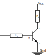
For a transistor to act as a switch it needs to be activated as the saturation region. When switched on in saturation the transistor acts as though it is a closed switch allowing current through the load.
If the load being switched is an inductive device, such as a motor, solenoid or relay then a diode should be connected in the reverse direction across the load to prevent any back EMF from damaging the transistor.
Whilst the aim of this is to keep the maths to a minimum we need to use some simple formula to determine the appropriate value for the base resistor Rb. The key equation used here is Ohm's Law.
To work out the appropriate level of resistor you need to calculate the appropriate input current to saturate the transistor. The input is normally driven by a much higher current to ensure that it is well into this saturation region (eg. 10 times the minimum saturation base input current).
First we need to determine the current flowing through the resistor RL. Depending upon the type of device it may be possible to take this from the datasheet based on the current required to activate or operate the device. If this is not known - or we need to limit this current to protect the device then the resistance can be worked out using ohms law.
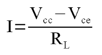
Vcc is the supply voltage, Vce is the voltage drop across the collector to emitter at saturation. The value of Vce can be found from the transistor data sheet.
The transistor data sheet needs to be checked to ensure that the maximum current through the transistor. On a lower power transistor this could be be quite low such as 100mA on a BC546, but on a high power transistor this could be as high as 15A on a TIP3055. If the Ic max value is too low then either a different transistor needs to be used or a resistor added to limit this current (if the rest of the circuit can work with a reduced current).
After working out the collector current the minimum base current can be found by looking at the gain factor of the transistor. The gain factor is listed on the data sheet as hFE or β
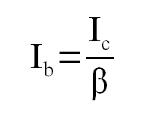
The formula of relationship between the collector current and the base current is:
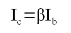
which we transpose as:
The gain for a transistor is not constant, but for a switch using the lowest value will ensure the transistor if in the saturation region. Example gain values are 200 to 450 for a BC546 transistor or 45 for a TIP3055 transistor.
To ensure that the transistor is fully switched on even if the load changes then we normally multiply the base current by a factor of 10. If the base current at ten times the required base current exceeds the maximum base current then a value below the maximum base current should be used instead.
To provide the appropriate size resistor we use the following formula.
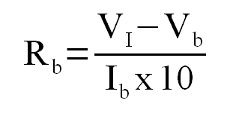
Where VI is the voltage input to the base resistor.
See my example projects using transistor switches
Please view the copyright information regarding use of the circuits.

