- Home
- Learn Linux
- Learn Electronics
- Raspberry Pi
- Programming
- Projects
- LPI certification
- News & Reviews

Google Ads
This is a very simple electronic circuit. This is something that I created with my 6 year old daughter as an introduction to electronics. I wanted something that was simple enough that she could learn from it whilst providing something that she can use as a demonstration for show and tell at school. This circuit is a low light sensor which turns on an LED when the light level drops.
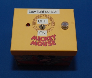
As you can see from the above photo this circuit has made the use an old cardboard box that we had available. The box used previously held a mug and was just about the right size for this project.
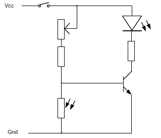
The circuit is a simple transistor switch circuit using a light-dependant-resistor (LDR) in a potential divider circuit. As the light to the LDR falls the resistance increases and so does the voltage at the base of the transistor switching it on.
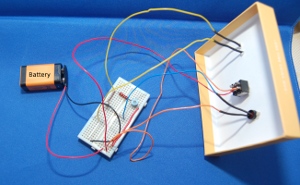
The circuit is mounted on a small breadboard which is stuck inside the box. This meant that the circuit could be made easily. The switch, LED and LDR were mounted on the box and connected to the circuit using wires solded to the connectors. My daughter soldered the wires and put the heat shrink sleaving over the wires, although it did involve some hand-holding (literally).
The LED and associated resistor could be replaced with a buzzer as an alarm when light falls below a certain threshold.
Please view the copyright information regarding use of the circuits.

