- Home
- Learn Linux
- Learn Electronics
- Raspberry Pi
- Programming
- Projects
- LPI certification
- News & Reviews

Google Ads
As explained in the earlier page on the MOSFET switch it is possible to use a MOSFET to switch larger loads. It's also possible to use a MOSFET to switch different voltages.
This video explains how MOSFET switcsh can be used to change the voltage output for logic signals. This includes increasing a voltage from 3.3V to 5V, creating an open drain switch for protocols such as I2C and as a bi-directional logic level shifter for communicating between a Raspberry Pi / Raspberry Pi Pico and an Arduino.
The first example shows how a voltage can be increased from 3.3V from a Raspberry Pi to the 5V needed for a NeoPixel to run at full brightness. Although it is sometimes possible for this to work without a level shift increasing the voltage to 5V will make the circuit more reliable.
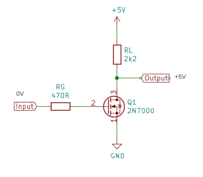
The standard MOSFET switch above shows a common simple configuration for one direction MOSFET level shifter. It comprises of one N-channel MOSFET, and depicts two resistors. The resistor RL is used as a pull-up ressitor to the higher voltage power supply. The resistor at the gate RG is a resistor used to prevent damage to the device controlling the switch, such as a Raspberry Pi or microcontroller. This circuit is inverting in that the output is high when the input is low and the output is pulled low by the MOSFET when the input voltage is high. In the case of NeoPixels this can be compensated for in software.
For the program code and a detailed demonstration see the Raspberry Pi PixelStrip / Neopixel GUI software page.
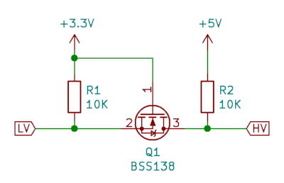
There are some commercial bi-directional logic level shifters available. This is the schematic diagram of just one of the level-shifters on a 4-bit level shifter from Adafruit.
To understand this we will consider 3 different states.
First with no signal on either side, which is that they are either output a high or reading it as an input. Effectively this means there is nothing pulling the signal level down so it should output a logic-high at both ends (3.3V at the Raspberry Pi and 5V at the Arduino).
The voltage of the gate to source junction (pins 1 to 2) is at 0V (both are at 3.3V) so the MOSFET is switched off. Therefore the output at the LV end is based on the R1 which pulls-up to 3.3V and the output at the HV end is based on R2 which pulls-up to 5V. So both ends are at logic high.
Therefore if the output of both is high (or they are using this an input) then both ends are at their corresponding high voltage.
When the low-voltage side wants to output a low then it connects it’s output to 0V through the open drain. This sets the source of Q1 at 0V and with 3.3V at the gate so the MOSFET turns on. The high end output (which is at the drain) is then pulled-down through Q1. So this gives a logic low at the HV side.
I’ll now show the we can handle the tranisition from a high-signal at both sides (the first state we talked about) to the 5V side setting the bus to low.
The higher-voltage side now outputs a low by pulling it’s end down through the open drain. The drain-substrate diode of the MOSFET is pulled down (the one shown inside the circle of the MOSFET) so that can conduct from the source to the drain (the opposite of the way it conducts when as a switch). Then when the source voltage falls below the gate voltage the MOSFET switches on. With the MOSFET switched on then both the LV and HV sides are at 0V giving a logic-low at each side.
Through these different states the circuit can work bi-directionally between hardware designed for different voltage levels. The example used was for I squared c, but this can equally be used for other protocols and was used in my earlier video communicating between a Raspberry Pi and an Arduino using SPI.
To see an example of the level-shifter in use see Raspbery Pi Pico with MCP23008 GPIO expander.
Please view the copyright information regarding use of the circuits.

