- Home
- Learn Linux
- Learn Electronics
- Raspberry Pi
- Programming
- Projects
- LPI certification
- News & Reviews

Google Ads
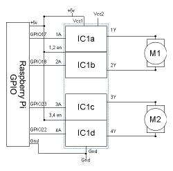
In the previous article we looked at using a H-bridge IC to handle the direction of a DC motor, but we had not explained how to control the speed. This looks at how we can use Pulse Width Modulation (PWM) to vary the speed of a motor using a digital signal. The circuit diagram is the same as the previous article repeated below.
We have now built a circuit that will allow us to move the motors forwards and backwards, but we also need to be able to control the speed. A common way to change the speed of a DC motor is to change the DC voltage. As the voltage increases the magnetic field is more powerful and as it decreases it produces a less powerful magnetic field. The circuit we have made is based on switching the supply on and off rather than been able to provide a variable voltage, so what we need is a way to make this digital on-off signal appear as though it's an analogue DC voltage.
There is a technique that can be used that can change the speed of the motor by switching the supply on and off very quickly. In fact this is a technique that can be used in other circumstances to create an analogue output from a single digital signal. This is explained in the video below.
The technique is called Pulse-width modulation (PWM). It works by switching the voltage on and off very quickly. The ratio of time that the voltage is switched on compared to it being switched off provides an equivalent voltage.
This is easier to understand by looking at a waveform diagram. The diagram below is simplified from what the waveform actually does which is done to make the explanation clearer. The waveform shows the voltage on the y-axis over time in the x-axis. The time is in milliseconds as this all happens very quickly.

The blue waveform shows the output voltage used to drive the motor. It changes from 0V to 5V as the controller is switched on (this shows only one direction – the other direction would be reversed).
The red waveform shows the equivalent voltage based on the percentage of time that the actual voltage (blue) is turned on.
We start with the actual voltage completely off. The blue line (actual voltage) is at 0v as is the red line (equivalent voltage). Then the power is applied for three tenths of a cycle and then turned off for seven tenths of a cycle. This means that the equivalent voltage is three tenths of the voltage which is 1.5V. Then the width of the PWM pulses increases so that it is on for six tenths and off for four tenths which gives an equivalent of six tenths of the supply which is 3V. Finally the supply is fully on giving an equivalent voltage of 5V. This is greatly simplified but shows how increasing the width of the PWM pulses increases the voltage applied to the motor. The waveform above shows how a motor could be accelerated, although in reality this would be over a much longer time period.
The waveform shows the voltage applied to the motor but it does not necessarily reflect what actually happens with the motor. In reality the motor will not turn at all until the supply is sufficient to get over the physical resistance posed by the motor and the wheels connected to it. This is very different to how a stepper motor (different type of DC motor) is controlled which allows the motor to be moved in individual steps corresponding to different coils being powered on in the correct sequence.
It is possible to provide PWM using the hardware or software. Hardware based PWM uses circuitry within the processor to turn the pins on and off as appropriate, whereas software based PWM does it using software running on the processor. Hardware driven PWM is usually preferred as it uses minimal CPU load to implement, however the library chosen for this does not currently support hardware based PWM. The module suggested is RPi.GPIO which uses software based PWM, but in future versions of the RPi.GPIO library may change to hardware based. Also note that even with hardware based PWM depending upon what else is running there is no guarantee that the code controlling the PWM will be running when required. An alternative would be to use an Arduino (with or without a Raspberry Pi) which can be much better at responding to events in real time.
More details about RPi.GPIO is available from Python package - RPi.GPIO
This is an example of the use of PWM to control a model railway locomotive. This is based on my project: model railway automation with Raspberry Pi
Please view the copyright information regarding use of the circuits.

