- Home
- Learn Linux
- Learn Electronics
- Raspberry Pi
- Programming
- Projects
- LPI certification
- News & Reviews

Google Ads
The direction of a DC motor is determined by the direction of the current through the motor, so by reversing the positive and negative supply we can make the motors change direction.
The h-bridge configuration is a common way to change the direction of the power supply. The h-bridge is named as it is shaped a little like a letter H and uses two pairs of switches that need to be switched together. It is easiest explained using the video below.
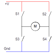
The switch pairs are diagonally opposite to each other. Each pair of switches need to be closed at the same time. So on the diagrams below S1 and S4 form one pair and S2 and S3 the other pair.
This is the H-bridge in it's off position. All four switches are turned off and no power is provided to the motor.
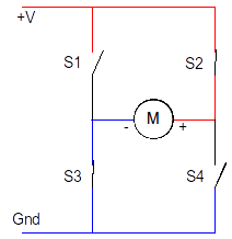
When S1 and S4 are closed the positive supply goes to the left of the motor and the negative to the right. The motor will then work in one direction.

To change the direction switches S1 and S4 need to be opened and then S2 and S3 closed. The positive supply is now provided to the right of the motor and the negative to the left, so the motor will now turn in the opposite direction.
It is important that S1 and S3 are never closed at the same time and the same with S2 and S4. Switching these on together would create a short circuit across the power supply.
The H-bridge circuit could be made with discrete transistors / FETs, an Integrated Circuit or even relays (although relays would make it difficult to implement speed control). For small motors then it's usually easiest to use a H-bridge Integrated Circuit (chip).
The SN754410 integrated circuit is a quad half-H driver which provides four modules. Combining two of these modules provides a single H-bridge circuit. We can therefore use one IC to control two motors.
The PIN layout is shown below:

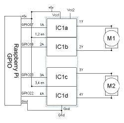
The logical diagram shows how the four half-bridge modules can be configured as a pair of H-bridge controllers.

To check that the IC is suitable we should refer to the datasheet available from the manufacturer (in this case Texas Instruments). According to the datasheet the IC can be used to switch up to 1A for supplies of 4.5V to 36V, and includes a separate power supply for the input to output. All inputs are compatible with TTL and CMOS logic, which will work with both the GPIO from the Raspberry Pi and the Arduino. The power supply for the IC needs to be 5v which is the same as the Raspberry Pi.
There are two different ways of using the input signals for the H-bridge controller.
One way is to have a single output for the motor direction which is inverted between the two inputs, and then use the enable pin to turn the motor on and off. So for example if you had a high direction input that would go to input 1A and inverted low at input 2A and the opposite to change direction. This will just require two inputs to the SN754410, but would need an inverter to be added to the circuit. Or this could be implemented by having three outputs from the GPIO with one being inverted.
The other option, which is the one we will use here, is to permanently enable the EN pin by connecting it to high and then using the two inputs to turn the motor on and off as well as to determine the direction. This is achieved by setting both 1A and 2A to low, which is the off state and then turning one of these high to turn the motor on and set the direction.
The diagram below shows how the GPIO can be used to control the SN754410 H-bridge motor controller.
It can be built on a breadboard using a Raspberry Pi GPIO cobbler as below.

It is also available on a PCB based on the Ryanteck motor controller circuit board.

Motors are electromagnetic devices. This means that they use the electronic current to create a magnetic field which causes an action, in this case turn the motor around. When the power is removed the magnetic field will collapse, or if the motor continues to turn then it can act as a generator. When this happens there can be voltage spike caused by the back EMF (electromotive force) which could damage sensitive electronic components. It is normal to connect a diode in the reverse direction across a magnetic load to prevent the back EMF from damaging the electronic circuitry. These have various different names including flyback diodes, freewheeling diodes, suppressor diodes or clamp diodes.
The datasheet for the SN754410 IC shows the internal circuitry based on the diagram below. It shows two diodes connected in reverse across the transistor output which will help to dissipate the voltage spike. However the same datasheet also shows an example circuit diagram where external diodes are connected.
Adding external diodes would only cost a small amount (typically a few pence per diode), however adding them to the breadboard made the circuit more complex and harder to follow. They are not included in the motor controller board. If you are using the SN754410 for larger motors then I would suggest adding external diodes to provide additional protection, but it does not appear to be necessary for small motors. There is also an alternative IC the L293D which includes clamp diodes, although that IC is less readily available.
This is an example of the use of a H-Bridge to control a model railway locomotive on a train set. This is based on my project: model railway automation with Raspberry Pi
Please view the copyright information regarding use of the circuits.

