- Home
- Learn Linux
- Learn Electronics
- Raspberry Pi
- Programming
- Projects
- LPI certification
- News & Reviews

Google Ads
There are different ways of creating electronic circuits depending upon tools available and how permaenent a solution is required.
For the most basic circuits you can wrap wires together or join using wires and croccodile clips, but once you go beyond a few basic components that gets very difficult if not impossible.
When creating a new circuit it is more common to first create a prototype using a breadboard or similar before the circuit is made permanent using solder. This allows any problems to be identified at an early stage where it is easier to change the design than removing soldered components.
The final design is normally created onto something more permanent such as a printed circuit board, or strip-board.
A simple circuit can be created by hammering nails into a piece of wood and then wiring / soldering between the pins. This is the way that I created one of my first ever circuits at school whilst studying for my GCSCs. More sophisticated systems using specialist boards and special wire-wrap tools.
This is a good way to build very basic circuits when first starting out in electronic circuits. It is also a good way of teaching as the circuit diagram can even be drawn onto the wood showing the circuit diagram compared with the real components. I would not recommend this technique for more complex circuits and in particular once you start using integrated circuits breadboards are usually much better.
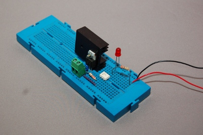
Solderless breadboards (also known as plugblocks or plugboards) are a good way of creating temporary circuits to allow testing prior to commiting with solder. They consist of a plastic board with a matrix of holes. These are then connected in small rows so that components plugged into the same section are connected together.
Breadboards are very easy to use and don't damage the components. Integrated circuits (ICs) can be easily inserted and wired to other components. Some are also available with mounting frames for potentiometers etc. Solid core wires are needed for connecting to the breadboard (if you normally use the more flexible multi-core wires then you should get some solid core for the breadboard. If you find that you are creating a lot of circuits then it can be easier to buy a box of pre-cut lengths, although these are more expensive than just cutting standard wire to the appropriate length.
The video below demonstrates how to create a breadboard stand which can be used to connect using 4mm banana plugs for an external power supply or multimeter.
The 25 minute electronic training session used solderless breadboards to allow the learners to build a buzzer circuit.
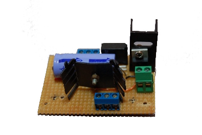 Stripboard or Veroboard (trademark name of company that first invented it) provides a way of creating soldered circuits without the expense and complexity of creating a custom printed circuit board.
It is a board with a 0.1in (2.54mm) grid of holes with strips of copper running in a single direction across each row. Normally these extend the full length of the stripboard, but there are some versions with a break in the copper tracks suitable for mounting integrated circuits, or some that replicate the layout of a breadboard.
This is a very common way of creating permanent circuits for hobby electronic enthusiasts who may not have the equipment for creating a complete printed circuit board.
Much of the Computer controlled disco and theatre light project is created using stripboard.
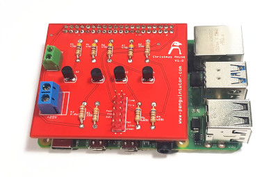 It is possible to create your own printed circuit boards from basic components. To make yourself involves using some fairly nasty chemicals and is quite difficult to get consistant results. It is often better to get these made by a professional printed circuit board manufacturer which are now inexpensive.
Designs are normally created using a circuit design tool such as Fritzing or KiCAD. These are then exported as gerber files which are sent to the fabricator. These are explained in the projects below.
One thing to be aware of is that many of the PCB manufacturers are in the far east and whilst their production costs are low there may be significant costs and lead-time for shipping depending upon the shipping option chosen.
The following are some tools that can be used for designing circuits from basic design, breadboard design and creating printed circuit boards.
For most beginners I'd recommend getting a breadboard for building temporary circuits or for testing a design. A good next step is to transfer the design to a stripboard if a permanent version is required. If you go beyond the capability of stripboard then PCBs are now easy to design and can be manufactured cheaply.
Please view the copyright information regarding use of the circuits.

