- Home
- Learn Linux
- Learn Electronics
- Raspberry Pi
- Programming
- Projects
- LPI certification
- News & Reviews

Google Ads
Taking the leap from manual operation to full computer control is one of the most rewarding upgrades you can make to a layout. As part of my ongoing series covering both indoor (OO Scale) and outdoor (G-Scale) model railways, this guide dives into the technology and tools behind layout automation. We will be exploring how to use a Raspberry Pi to take charge of traditional analog trains, utilizing electronic sensors to precisely track train positions and automate movement across the track.
This is part of my projects on building an indoor (OO Scale) and outdoor (G-Scale) model railway.
This will look at the technology behind model railway computer control and automation and some of the tools that can be used. This is primarily looking at using a Raspberry Pi or Arduino, controlling an analog train using sensors to detect the position of the train.
This video introduces my G-Scale outdoor model railway. It's work in progress, but it is now fully working with some automation as well as a web based IoT train control option. Using the web based version I can control the trains using my mobile phone or laptop.
Please Subscribe to my channel if you find these videos useful.
In this first part to the video I cover power supplies and the need to convert form the AC (Alternating Current) power supply in many model railway transformers to DC (Direct Current) needed to control the DC motors.
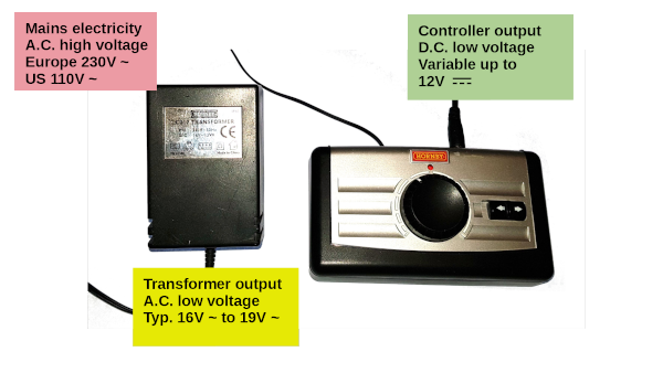
The image below shows a plug-in transformer and a model train controller. These are typical for analog model railways (in my experience with both OO / HO scale and Garden Scale outdoor railways), in that the plug-in transformer outputs an AC voltage. This is different to most other plug-in power supplies which convert the voltage to DC within the power supply. For model railways the controller is responsible for converting the AC to DC which is required to control the DC motors inside the model train.
The AC waveform changes polarity from positive to negative. This is shown in the top of the diagram below. This first needs to be converted to a DC voltage using a bridge rectifier which gives the second waveform. It can then be smoothed using a capacitor to create the third rectifier. If this is being used to power a microprocessor then it may need to go through an additional voltage regulator to ensure a consistant voltage.

A bridge rectifier is an arrangement of 4 diodes (eg. 1N4001) configured so that the output is always in the same direction giving a DC voltage.

Rather than constructing this from four diodes it is usually easier to buy a bridge rectifier integrated into a single component. The SKB2/02 or KBP series bridge rectifier is shown in the video, although there are other bridge rectifiers depending upon the amount of current required.
Please Subscribe and click the bell icon to be notified of my future videos.
To change the direction of a DC motor uses in a model train then the polarity of the supply needs to be reversed. For automation this is normally achieved using a H-Bridge which can swap the polarity to the track / motor without needing a negative power supply. The H-Bridge works by having 4 internal switches (usually MOSFets within an integrated circuit). When the switches are all off then there is no power to the track. When diagnally opposite switches are turned on then the polarity is in one direction, when the other pair of diagnally opposite switches are turned on then the polarity is reversed. This is best illustrated through the following diagrams.
In this diagram the switches are all off so there is no power to the motor.

In this diagram one pair of diagnally opposite switches are on so there is power to the motor in one direction.

In this diagram the opposite pair of diagnally opposite switches are on providing power in the opposite direction.

It is important that the switches that are in-line with each other (on the left or right) are never turned on together as that would create a short circuit. When a H-Bridge integrated circuit is used then this protection is included within the package.
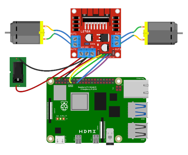
For model railways then my preferred H-Bridge is the L298N motor controller IC. This is available as an inexpensive motor controller board which is easy to connect to the Raspberry Pi or Arduino. An example board is shown in the photo below.

To make it easier to connect the Raspberry Pi to the motor controller I have created a board to mount them together. I designed the board in FreeCAD and printed on my 3D printer.

The board has mounting holes one one side for a Raspberry Pi, with our without a pimoroni Pibow case (the photo above shows with a PiBow coupe). The other space has mounting holes for 2 L298N h-bridge motor controller boards which can allow up to 4 motors to be controlled. Alternatively as shown, it can have one motor controller board and one mini-breadboard. The connections needed are one pair of GPIO ports per motor (one for forward and one for reverse) and a ground connection. The motor controller can be powered from an external supply (eg. 12V DC supply) in which case the power jumper can be left in place and it will take power for the board from that. If not then that can be removed and a 5V power connection be taken from the Raspberry Pi.

You may need to widen the holes using a drill depending upon the size of your mounting screws. A 3.2mm drill is a good size if using M3 screws.
Pulse width modulation is a technique to create a variable voltage using a digital output. It is often used on both the Arduino and Raspberry Pi to provide an equivelant analog voltage output.
The waveform below shows how different width pulses can be used to create a varing effective voltage when used to switch as 12V power supply to control a model train.

The source code to use PWM on the Raspberry Pi (using Python GPIO zero) and on the Arduino (using in-built pwm pins) is included below.
This episode looks at using reed swith and magnet to automate the model train so that it automatically stops at the station. The reed switch is a switch which is activated when a suitable magnet comes into range. Placing the reed switch in between the track and a magnet on the locomotive means that the Raspberry Pi can detect the train approaching the station and slow it down and stop it at the correct position.
There are different types of reed switches and magnets suitable for different situations. The following guide is a quick guide to some different types of reed switches and magnets.
Here is a list of the reed switches and magnets that I used for the video. These are all from CPC Farnell which is the UK retail branch of Farnell / Element 14. I don't get any monetization from these, but they are the one supplier that I used that has a good selection of different types that I could buy and try. I've also included a cheaper version of the mountable reed switch which is much cheaper than the 240V version and makes that an even better option for model railway control.
The final episode in this series covers using a Raspberry Pi and IoT to control the train using a web browser. This allows the train speed to be controlled using a mobile phone and a web browser. The program uses Python Bottle which acts as a web server.
The wiring for the Raspberry Pi to the L289N motor controller is shown below. This shows motors to represent the trains, which are actually wired through connections to the track for the model railway.
The software for the model railway controls has now moved to GitHub. See the following link, which includes details of how to install the code.
The interface is under development. It is designed for a mobile phone in portrait mode with the ability to control two trains.
Please Subscribe and click the bell icon to be notified of my future videos.
Also see:
To see future updates please:
Subscribe to the PenguinTutor YouTube Channel
Please view the copyright information regarding use of the circuits.

