- Home
- Learn Linux
- Learn Electronics
- Raspberry Pi
- Programming
- Projects
- LPI certification
- News & Reviews

Google Ads
If you're looking for a compact, microcontroller-based alternative to my original Raspberry Pi departure boards, this Raspberry Pi Pico W version is the perfect solution. Designed to integrate seamlessly with my wider model railway automation systems, this project uses a miniature OLED screen to display realistic, time-accurate station departures. I've also included a custom FreeCAD enclosure tailored for a G-Scale environment, though the 3D design can be adapted and shrunk down for OO scale or other smaller layouts.
This is a version of my model railway departure boards designed for use with a Raspberry Pi Pico W. This is an alternative to my Raspberry Pi version of the model railway departure board.
This is part of my projects on building an indoor (OO Scale) and outdoor (G-Scale) model railway. The FreeCAD design is based around G-Scale, but it would be possible to create a smaller version for other railways.
This project creates a station departure board using a miniature OLED display. This is controlled using a Raspberry Pi Pico which allows the current time to be used to make the display appear more realistic. This can be used in conjunction with the Raspberry Pi Model Railway Automation project.

This video explains how the OLED display is controlled by a Raspberry Pi Pico W using I2C. Details are provided of the code which is created using MicroPython. It also shows how it can connect to a web server or other authentication to display different train times.
Please Subscribe and click the bell icon to be notified of my future videos.
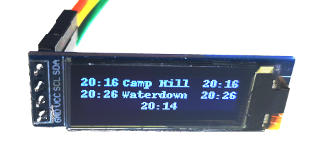
The OLED display is a miniature 0.91" display. The version that I used is the I2C model which has the fixed I2C address of: 0x3C.
The SSD1306 displays have a fixed I2C address of 0x3C. Unfortunately this means that it is not possible to control multiple displays on a single bus. To overcome that I have used two busses on the Pico, I2C0 controls display 0, and I2C1 controls display 1.
GP16 is SDA for display 0 (physical pin 21)
GP17 is SCL for display 0 (physical pin 22)
GP18 is SDA for display 1 (physical pin 24)
GP19 is SCL for display 1 (physical pin 25)
This image shows the wiring diagram. The pull-up resistors shown are optional, they may be required for longer runs.

The display stand is created in FreeCAD and then 3D printed. The video above shows the FreeCAD design speeded up, to learn more about FreeCAD see my Beginners guide to designing for a 3D printer using FreeCAD.
The design is created as 4 parts. The display is the main part that holds the SSD1306 I2C OLED display, a piece of transparent acetate should be glued across the front for waterproofing. The back fits into the back of the display. It is not waterproof so it should be held in place using hot melt glue or similar.
The stand is the post that holds up the display and can be used to run wires through. Finally there is an optional base. The base is not intended for use on the railway (which will be incorporated into the platform), but provides a way that I could stand it up for the demonstration.
Also see:
To see future updates please:
Subscribe to the PenguinTutor YouTube Channel
Please view the copyright information regarding use of the circuits.

