- Home
- Learn Linux
- Learn Electronics
- Raspberry Pi
- Programming
- Projects
- LPI certification
- News & Reviews

Google Ads
Lighting up your next maker project just got a whole lot easier—and more educational. Originally designed for The MagPi magazine, this custom Raspberry Pi Pico LED controller provides a straightforward, hands-on way to manage 5V to 12V lighting setups. Whether you want to illuminate a model railway, brighten up your camping gear, or experiment with COB-style LED strips, this through-hole board is built with simplicity in mind to help you learn the ropes. Best of all, by swapping in a Pico W, you can instantly transform this straightforward circuit into a smart, network-controlled lighting system right from your web browser.
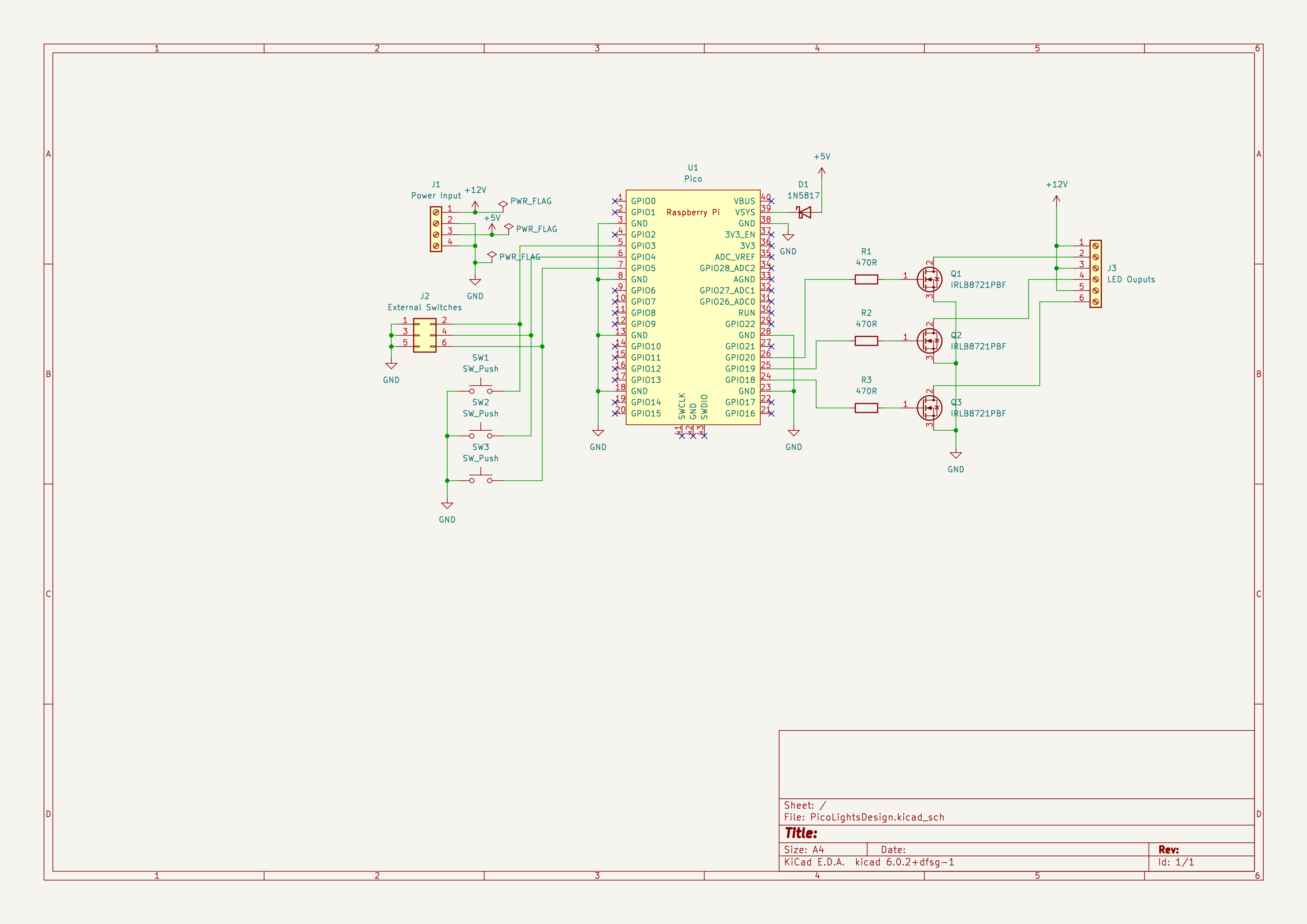
This project is based around a custom PCB created for a Raspberry Pi Pico. This was designed as a project for the The MagPi magazine
.The PCB is designed for 5V to 12V LED lights, with appropriate power supply. It can be used for camping, model railway lighting or COB style LED strips. If used with a Pico W (wireless version) then the microcontroller can act as a web server allowing the lights to be turned on and off over a network.
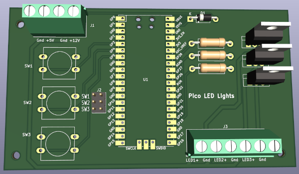
The circuit is intentionally simple using THT components as ths is intended for educational purposes, although can be (and is) used as a complete project. Please note that there is no authentication included and the only security to prevent others from controlling the lights is your WiFi security.
The Pico Lights PCB and the Pico Lights Plus PCB are closely related. They were actually designed together, although I made different decisions for the two boards. The plus version is the one I intended to create, however it was too complex for the magazine tutorial I was writing at the time, which is why I created a simplified version. I then expanded the circuit to create the one called Pico Lights plus.
The main difference between the boards are the additional LEDs, connectors and some additional voltage dividers on the plus board. See further down this page for more details about the Pico Lights Plus.
Click the image for a larger version.
This is the list of components needed for the project. This is often known as a Bill of Materials, or BOM. An example supplier is provided for each component, but can be purchased from a variety of different suppliers.
| Description | Quantity | Comments | Link |
|---|---|---|---|
| Raspberry Pi Pico W | 1 | The Pi Hut - Raspberry Pi Pico W | |
| 470Ω resistors | 3 | ¼ Watt | The Pi Hut - 470Ω resistors |
| 1N5817 schottky diode | 1 | Similar schottky diodes can be used | CPC 1N5817 |
| PCB Switches | 1 | 12mm square | The Pi Hut PCB Switches |
| PCB screw terminals | 5 | Different sizes can be used for inputs vs outputs | PCB screw terminals |
| IRLB8721 MOSFET | 3 | Alternative: IRL520 | The Pi Hut MOSFETS |
| 12V LED light strip | 3 | Alternative: Model railway lighting | Amazon UK - 12V LED light bar |
| 12V power supply | 1 | Minimum 2A | CPC 12V 5A power supply |
| 2.1mm jack to screw terminal | 1 | The Pi Hut DC 2.1mm to screw terminal | |
| DC-DC boot buck converter | 1 | Ensure a 5V for powering a Pico | The Pi Hut 5V buck-boost converter |
| Dual male header pins | 1 | Cut down to 3x2 | The Pi Hut 40-pin male headers |
| 20-pin female header pins for Pico | 2 | Or cut-down larger strips | Ebay 20pin female headers |
| 20-pin male header pins for Pico | 2 | Or cut-down larger strips | The Pi Hut male headers |
| Alternative 5V LED lights | |||
| 5V LED COB light strip | 3 | Alternative to 12V lights | The Pi Hut 5V COB LED light strip |
| 5V power supply | 1 | Alternative power supply for 5V lights | The Pi Hut 5V 4A power supply |
You will also need some wires and solder.
If using a battery or a different power supply without over current and short circuit protection then it is strongly advised that an inline fuse is used.
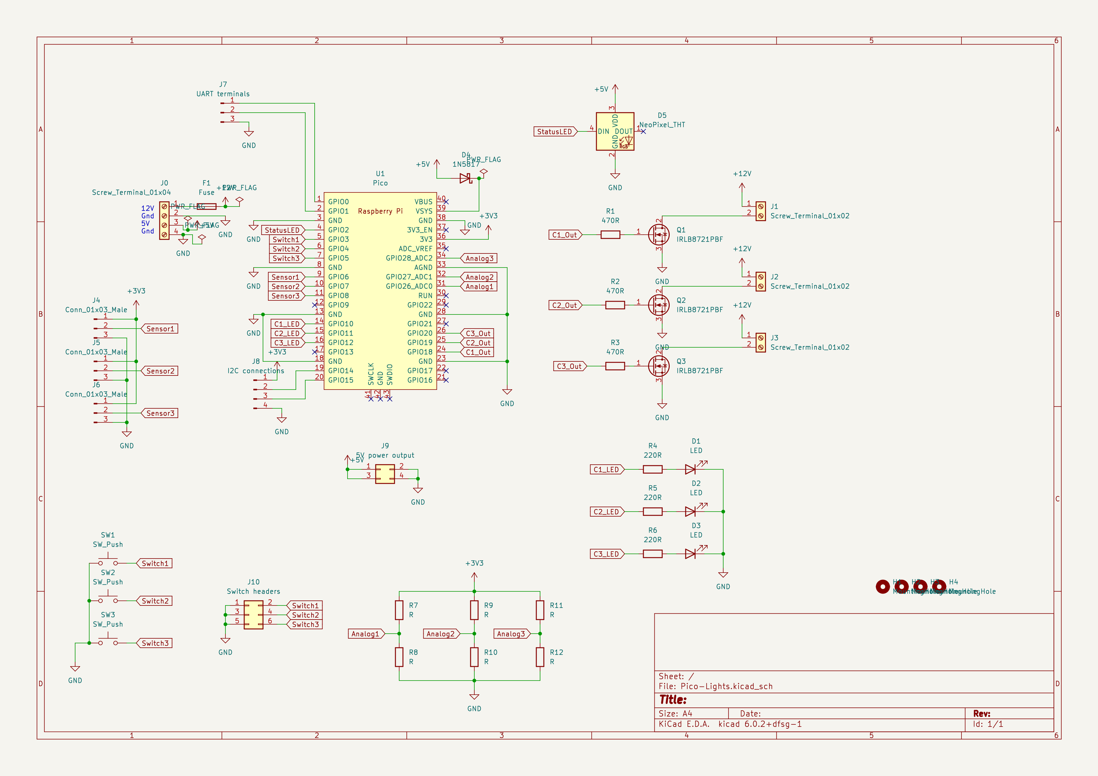
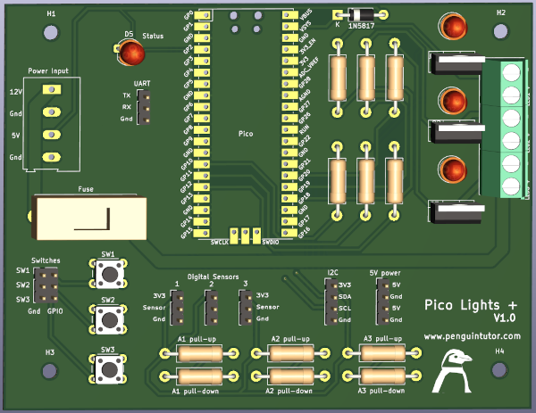
The Pico Lights Plus is an expanded version of the light controller. Featuring extra breakout ports for sensors and other inputs and a NeoPixel (RGB LED) status. It also includes a PCB mounted fuse for additional protection.
It is mostly compatible with the earlier version, but there are a few changes to the wiring, including the ordering of the outputs and the additional status LED.
Click the image for a larger version.
The LED outputs are controlled by GPIO pins 18, 19 and 20. These control a MOSFET which can switch a high load. The MOSFET used in the diagram is the IRLB8721PBF, but could also use other N-channel power MOSFETS. For example this would also work with an IRL520N or an IRLB8721. The choice of MOSFET is mainly down to availability, but check the datasheet for your preferred MOSFET to see that it is within the appropriate voltage and current limits.
The corresponding LED outputs are on GPIO 10, 11 and 12. You need to ensure that any code that is used to control the LED outputs also activates these LED outputs.
The NeoPixel (WS281x RGB LED) is connected to GPIO2. There is no buffer between the Pico and the NeoPixel. This is outside of the design spec for the NeoPixel, but should not be a problem with the NeoPixel being so close to the Pico. This may become a problem if you have a long wire between the PCB and the NeoPixel data in pin, but should work in most situations.
There are three potential divider configurations connected to the three analog inputs. These can be used with variable resistors such as light dependant resistors paired with a fixed resistor.
The PCB is designed for flexibility rather than size. Whilst it is fairly big, for most uses of the board that is not an issue: for use with camping light automation then the enclosure needs to be large enough for the buttons and for model railway use it can be hidden under the base board. It is instead designed for maximum flexibility (with lots of headers for external components) and to make testing easier with onboard buttons and status LEDs. This also makes it good for educational purposes.
The camping lights includes a custom designed enclosure, created in FreeCAD.
The enclosure is not designed to be waterproof, but does use waterproof connectors so that the lights can be mounted in a tent or somewhere that is open to the elements. The lid is held in place using screws and knurled nuts which are sunk into the enclosure using heat.
The waterproof light connectors use different connectors depending upon where they cannect. I used Pro Elec connectso which are rated as IP68. These are shown in the diagram below:
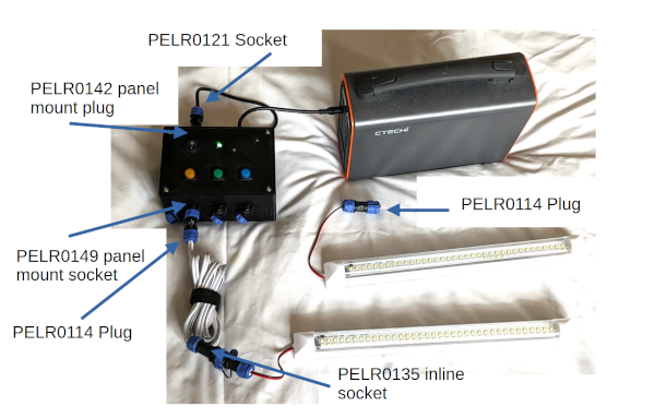
There is also an extension lead which uses:
For some of the connectors with small wires (eg. to the LED lights) then I did add a grommit inside the connector to help clamp on the wire. This was 3D printed using TPU flexible filament.
The Pico Lights and Pico Lights Plus PCBs can also be used for other projects. This includes Raspberry Pi Pico Christmas Tree star project.
To see future updates please:
Subscribe to the PenguinTutor YouTube Channel
Please view the copyright information regarding use of the circuits.

